What are the Working Principle and Structure of Centrifugal Pump?
1. The working principle of centrifugal pump
The impeller 2 is installed on the pump shaft 1, and there are several curved blades on the impeller. The pump shaft is acted on by external force to drive the impeller to rotate in the pump housing 3. The liquid enters the center of the impeller vertically from the inlet 4 in the axial direction, passes between the blades and enters the pump casing, and finally discharges from the liquid outlet 5 of the pump along a tangential line.
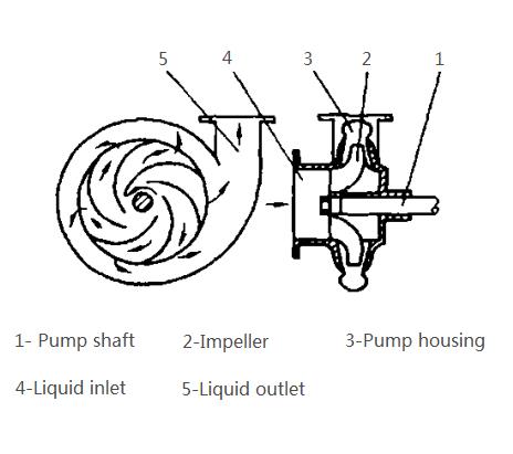
Centrifugal pumps are mostly driven by electric motors. Before starting the pump, the pump should be filled with the liquid to be conveyed. After starting, the impeller rotates to generate centrifugal force. Under the action of centrifugal force, the liquid is thrown from the center of the impeller to the outer periphery of the impeller, forming a high flow velocity (15-20m/s), and then decelerates in the shell, undergoes energy conversion, reaches a higher pressure, and then enters from the outlet Piping. After the fluid in the impeller is thrown out, a vacuum is formed at the center of the impeller. One end of the liquid inlet of the pump is connected to the center of the impeller, and the other end is immersed in the liquid being transported. Under the action of the pressure difference between the liquid surface pressure and the pressure in the pump, the liquid enters the pump through the liquid inlet, filling the position of the discharged liquid. . As long as the impeller continues to rotate, the centrifugal pump will continuously suck and discharge liquid.
When the centrifugal pump is started, if the pump casing and the liquid inlet pipe are not filled with liquid, the pump is filled with air. Since the density of air is much lower than that of the liquid, it is impossible to generate a large centrifugal force, resulting in a vacuum formed at the center of the impeller Not enough to suck liquid into the pump. At this time, although the centrifugal pump is started, the liquid cannot be transported. This phenomenon is called gas binding. In order to fill the pump with liquid, a bottom valve with a suction filter screen and a bottom valve check valve are installed at the bottom of the liquid inlet pipe. The filter screen prevents solid matter from entering the pump and damaging the blades of the impeller to ensure the normal operation of the pump. A valve to adjust the flow can be installed behind the outlet of the centrifugal pump.
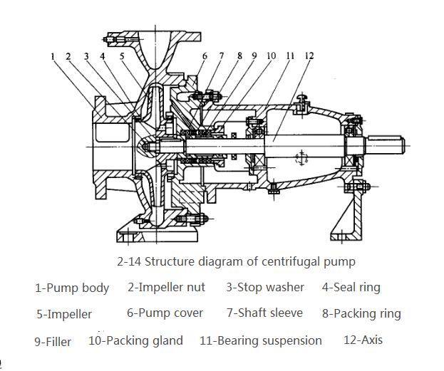
(1)Impeller. The impeller is a component that transmits the mechanical energy of the prime mover to the liquid, and improves the static pressure and kinetic energy of the liquid. As shown in Figure 2-15, the centrifugal pump impeller is often equipped with 6-12 blades. There are generally four types of impellers.
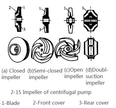
①The closed impeller, as shown in Figure 2-15 (a), has a front cover 2 and a rear cover 3 on both sides of the blade. After the liquid enters from the inlet in the center of the impeller, it flows to the outer edge of the impeller through the same flow channel of the two cover plates and the blades. This kind of impeller has higher efficiency and is the most widely used, but it is only suitable for conveying clean liquids.
②The semi-closed impeller, as shown in Figure 2-15 (b), has no front cover on the suction side.
③Open impeller, as shown in Figure 2-15 (c), the impeller is not equipped with front and rear covers. Semi-closed and open impellers are suitable for conveying slurry or liquids containing suspended solids. Because the impeller is not equipped with a cover, the liquid is easy to flow back when moving between the blades, so the efficiency is low.
④The double-suction impeller, as shown in Figure 2-15 (d), is suitable for large-flow pumps with good cavitation resistance.
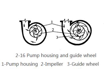
(2)Pump housing.The outer shell of the centrifugal pump is mostly made into a volute shape, in which there is a snail shell-shaped passage with a gradually enlarged cross section, as shown in Figure 2-16. The impeller rotates in the direction of the volute channel gradually expanding in the pump casing. Due to the gradual expansion of the channel, the liquid thrown from the periphery of the impeller at a high speed will gradually reduce the flow rate, reducing energy loss, and effectively converting part of the kinetic energy into static pressure energy. Therefore, the pump casing is not only a component that collects the liquid ejected from the impeller, but also an energy conversion device.
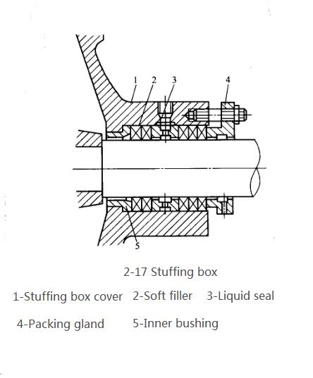
(3)Shaft sealing device. The function of the shaft seal is to prevent high-pressure liquid from leaking out of the pump casing along the circumference of the shaft, or outside air from leaking into the pump casing from the opposite direction. The commonly used shaft sealing device between the casing shaft and the pump casing has two types: packing seal and mechanical seal. Kind. The packing seal device used by the centrifugal pump is a stuffing box, also known as a packing box, as shown in Figure 2-17. In the figure, 1 is the stuffing box cover connected with the pump casing, and the soft packing 2 is generally oil-filled or graphite-coated asbestos rope. The packing gland 4 is tightened with screws, so that the packing is compressed between the cover and the rotating shaft to achieve the purpose of sealing. The inner liner 5 prevents the packing from being squeezed into the pump. In order to prevent air from leaking into the pump from the imperfect part of the stuffing box, a liquid seal 3 is installed in the stuffing box. The small tube on the stuffing box cover can communicate with the pump outlet, so that the high-pressure liquid in the pump flows through the small tube into the liquid seal ring. The introduced liquid can not only prevent air from leaking into the pump, but also provide lubrication and lubrication to the shaft. Cooling effect.
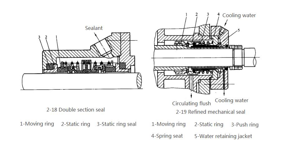
For pumps that have special requirements for transporting food, it is best to use mechanical seals, also known as end seals, whose structure is shown in Figure 2-18 and Figure 2-19. The main sealing element is composed of a moving ring and a static ring. The sealing is achieved by the close contact between the end faces of the moving ring and the static ring. It can be seen from the figure that the moving ring and the shaft
When it starts to rotate, the end face of the moving ring is close to the static ring, and the static ring is fixedly connected to the static ring seat. The close contact between the two ends is achieved by means of the compression element-the spring through the push ring. The tightness between the two end faces can be adjusted by a spring. The dynamic ring seal and the static ring seal are auxiliary sealing elements, which not only have a certain sealing ability, but also have a certain elasticity, which can absorb the vibration effect that has a bad influence on the sealing surface. Compared with packing seals, mechanical seals have the advantages of minimal liquid leakage, long service life, low power consumption, compact structure, and good sealing performance. The disadvantages are complex mechanical processing, high processing accuracy, strict technical conditions for installation, and high cost.
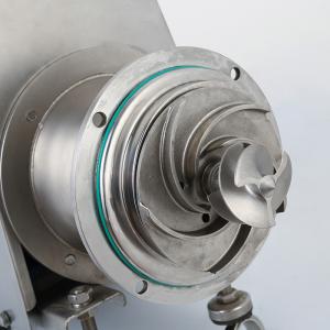
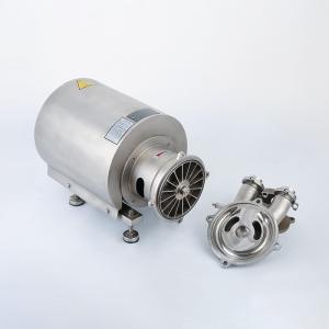
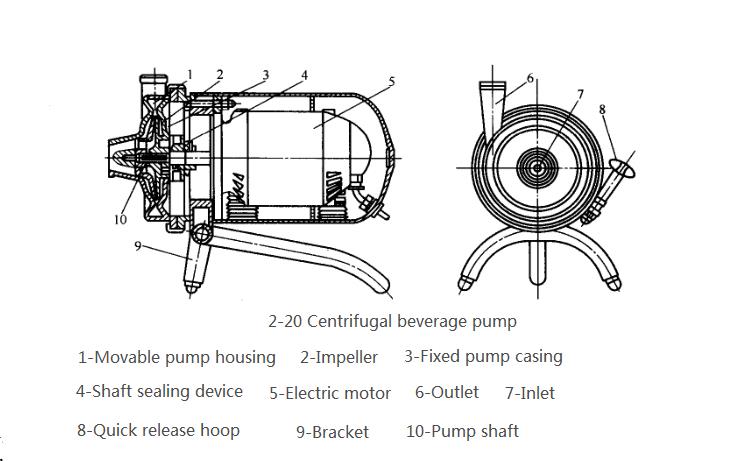
The shaft seal of centrifugal beverage pumps commonly used in food factories (Figure 2-20) often adopts impermeable graphite end face seal structure (Figure 2-21). All the components in the casing of the centrifugal beverage pump are made of stainless steel, often called sanitary pumps, used to transport puree, liquid, etc. The structure and working principle of the pump are the same as ordinary centrifugal pumps. The impeller adopts a closed impeller with fewer blades. The pump cover and impeller are easy to disassemble and assemble to meet the requirements of food hygiene and frequent washing in food factories.
Reference: https://www.chinakedun.com/Centrifugal-Sanitary-Pump-With-Open-Impeller-p.html
